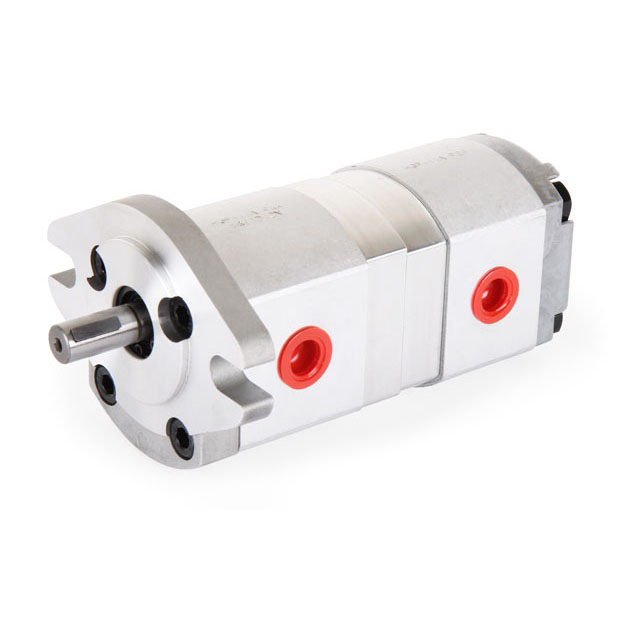
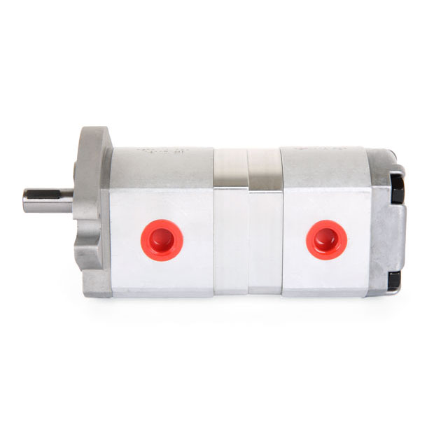
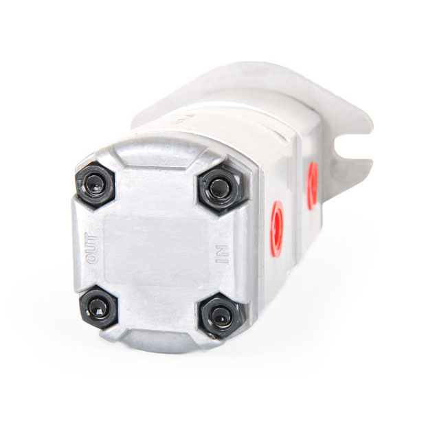
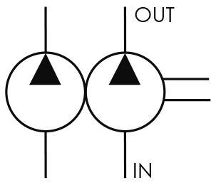
■ SCHEMATIC SYMBOL
■ ORDER CODES
HGP-11A - F 2 08 R - X2 - 4BDB - P1
1 - 2 3 3 4 - 5 - 6 - 7
1. Model Name : HGP-11A
2. Mounting :
F: flange type
L: foot type
3. Delivery Capacity :
05, 08, 1, 2, 26, 3, 4, 5, 6, 8
4. Rotation Direction :
R: clockwise
L: counter-clockwise
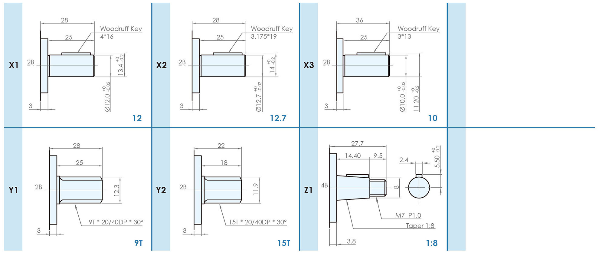
5. Shaft Type :
X: straight shaft
Y: spline shaft
Z: taper shaft
6. Flange Mounting Type :
2B: SAE 2-bolt
4BDA: DIN 4-bolt (type A)
4BDB: DIN 4-bolt (type B)
4BE: European 4-bolt
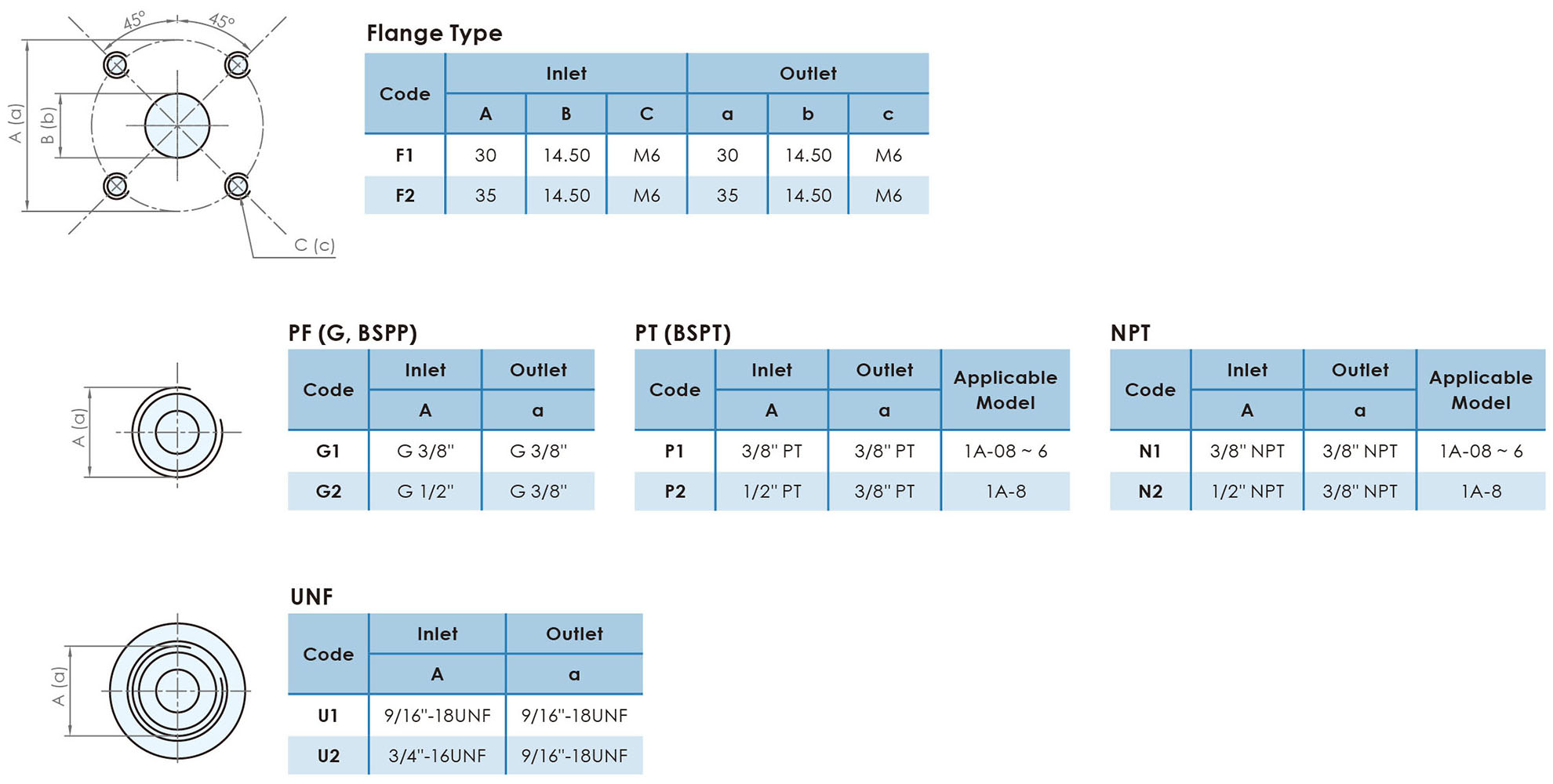
7. Inlet and Outlet :
F: flange type (F1~F2)
G: PF, G, BSPP (G1~G2)
P: PT (P1~P2)
N: NPT (N1~N2)
U: UNF (U1~U2)
■ SPECIFICATIONS
| Model | Accurate Displacement Capacity ( cc/rev ) |
Operating Pressure ( kgf/cm2 ) |
Max. Pressure ( kgf/cm2 ) |
Speed ( r.p.m. ) |
Weight ( kg ) |
||
|---|---|---|---|---|---|---|---|
| Rate | Max. | Min. | |||||
| HGP-11A-0505 | 0.5+0.5 | 210 | 250 | 1800 | 4500 | 1000 | 2.61 |
| HGP-11A-0808 | 0.8+0.8 | 210 | 250 | 1800 | 4500 | 1000 | 2.71 |
| HGP-11A-11 | 1+1 | 210 | 250 | 1800 | 4500 | 1000 | 2.81 |
| HGP-11A-22 | 2+2 | 210 | 250 | 1800 | 4500 | 600 | 2.91 |
| HGP-11A-2626 | 2.6+2.6 | 210 | 250 | 1800 | 4500 | 600 | 3.11 |
| HGP-11A-33 | 3+3 | 210 | 250 | 1800 | 4500 | 600 | 3.13 |
| HGP-11A-44 | 4+4 | 210 | 250 | 1800 | 4000 | 600 | 3.17 |
| HGP-11A-55 | 5+5 | 210 | 250 | 1800 | 3200 | 600 | 3.21 |
| HGP-11A-66 | 6+6 | 210 | 250 | 1800 | 3200 | 600 | 3.41 |
| HGP-11A-88 | 8+8 | 170 | 210 | 1800 | 3200 | 600 | 3.61 |
* HGP-11A-05 and HGP-11A-26 do not belong to regular products. Customized service can be provided.
* Weight is for reference.
■ DIMENSIONS ( unit : mm )
HGP-11A-2B

HGP-11A-4BD, 4BE

■ DIMENSION of SHAFT ( unit : mm )
■ INLET & OUTLET SIZE
